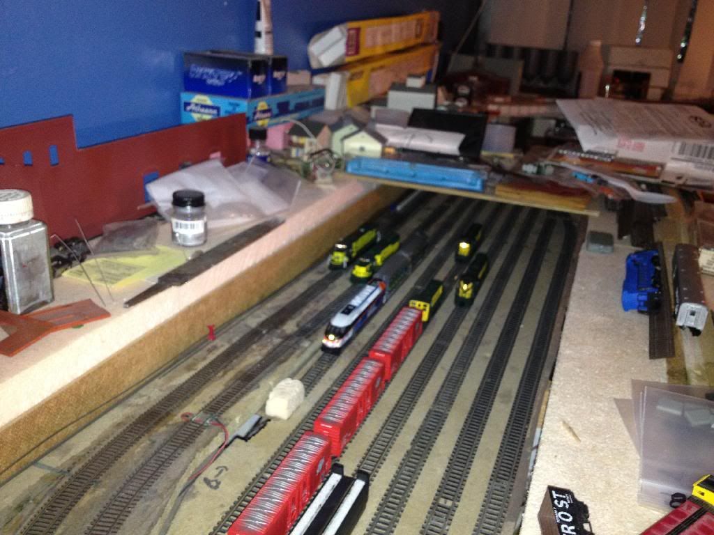
Sunday, March 13, 2016

Control Panel Construction: phase two

As some of you know I have been spending far too much time in the bathroom lately. Renovating, not as a fan! Unfortunately the only slack time I had to work that in to was layout time. So progress has been slow.

Until today.

Next week I'll hopefully get to start tiling, if a supplier pulls their finger out, but this weekend I got to spend some time working on my layout at home. And control panels were the project of choice.
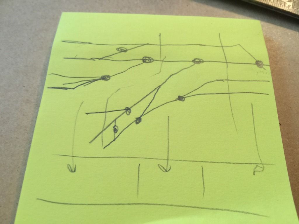

 The Plan for the Center End of the Layout

The most complex arrangement of control switches will go here. The end of the layout will have three panels; west end of branch, industrial tracks, and east end of branch.
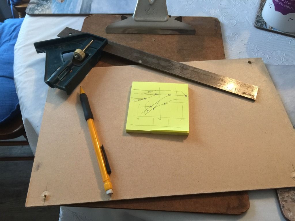

Ready to Begin

Simple tools; a square, a pencil, and the plan...
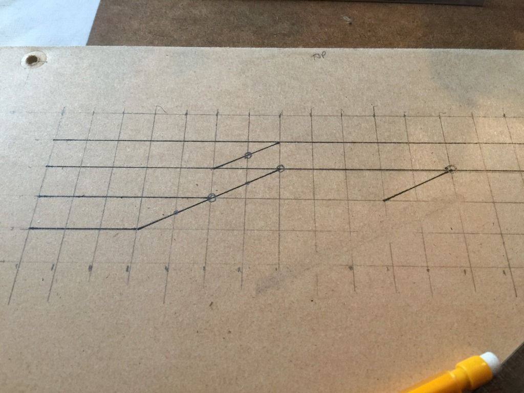

 West End Branch Panel

I drew half-inch grid lines on the panel board, then plotted the track lines. One half inch is about the minimum for two toggles switches to be mounted side by side. Dots are for turnout control switches.
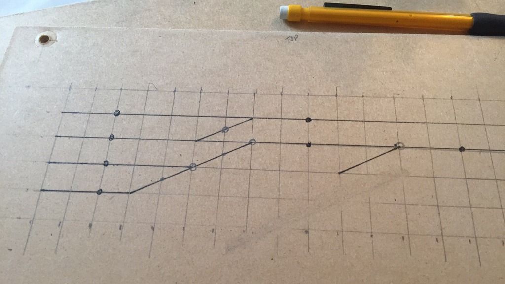

West End Branch Panel with Power Control Switch Placement

I added dots where track power switches will be placed. The spur in the center will lead directly to another turnout on the industrial track...
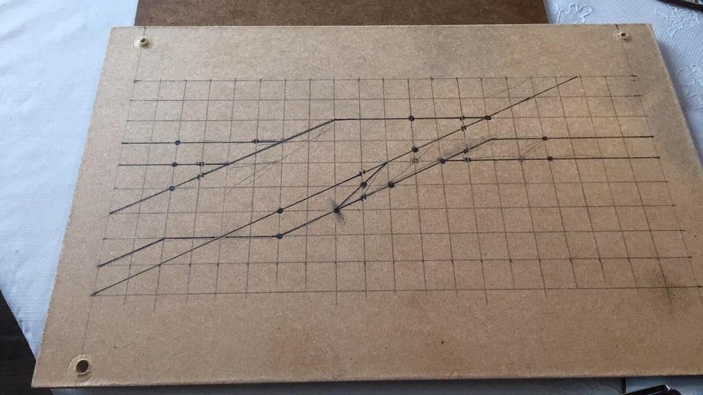

 Center Panel Prior to Drilling

Center panel for the industrial tracks; most of this has not been laid yet as it is code 40 hand laid!
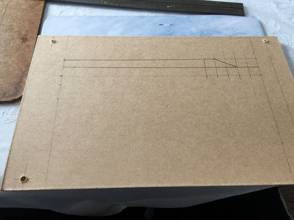

East End of the Branch

Third panel for this location; very simple, but mostly just keeping the fascia complete. Turnout is not powered yet, and way down in the list.
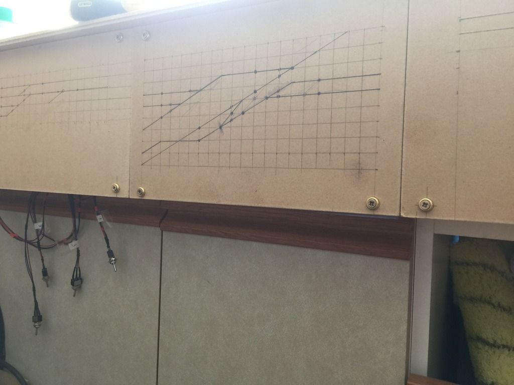

All Three Panels In Place


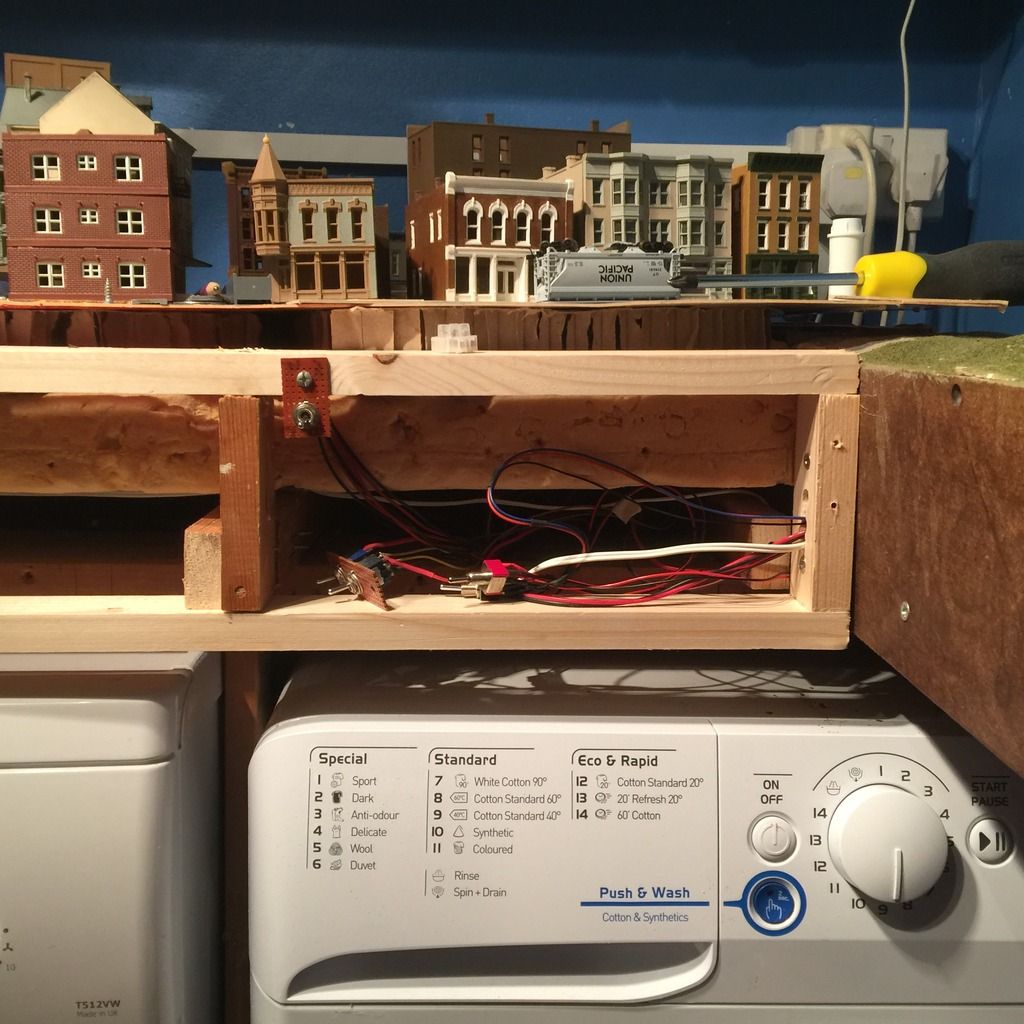
I put the panels back in place as I was not ready to start drilling them yet, and felt they were safest out of the way where they belong. The switches hanging under the panel on the left power the branch line turnouts, and will be mounted once the holes are drilled.

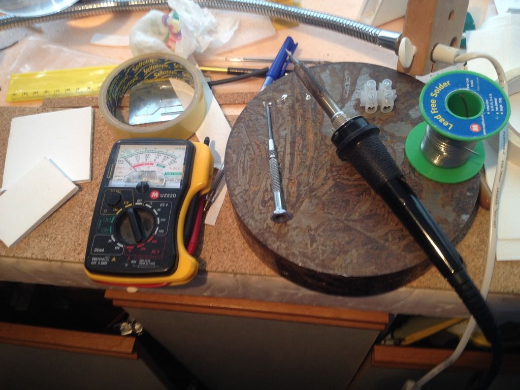
Hopefully I will get the opportunity to drill some of the holes and mount the switches that are already installed, to get them to where they need to be. Then it is on to soldering track power control switches to give me the ability to switch tracks between DC and DCC, something I have been wanting to do for a very long time!

Saturday, January 2, 2016

Control Panel Construction - phase one

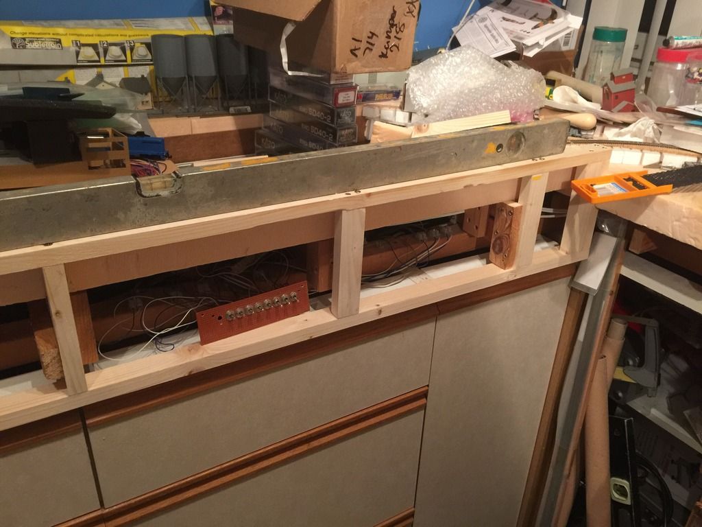
And they have to start somewhere. In this case, it's the framework:


First section of control panel frame in place

This will give me a great mounting for the control panel and ad about an inch or so of city space on the front of the layout.


Lower-level view of the frame

The framework is in place and mounted, showing most of the length of the frame.


Joining to the layout

This will be the trickiest transition to finally get right, as I have been scenicking this area already...


The other side

The other side of the control panel frames are up; now to the third side and panels themselves...


The left-hand end

to the left of this section will be the lift out, with the bridge.


The right-hand end

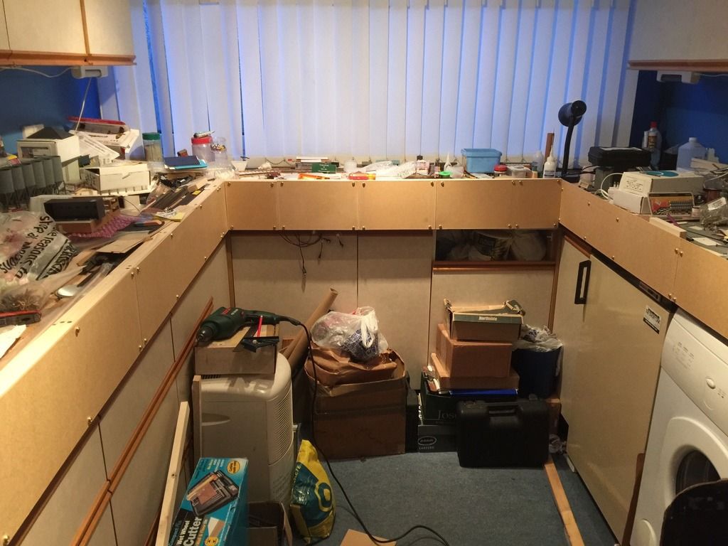
I've been using the switch controls for most of the time the layout has been built, and they will finally get a proper panel! I took advantage of the New Year's holiday and decided to work on the control panel fascias and clear up the layout room.


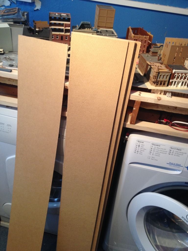
The local lumber store cut the strips into six and half and seven and a half inch strips.


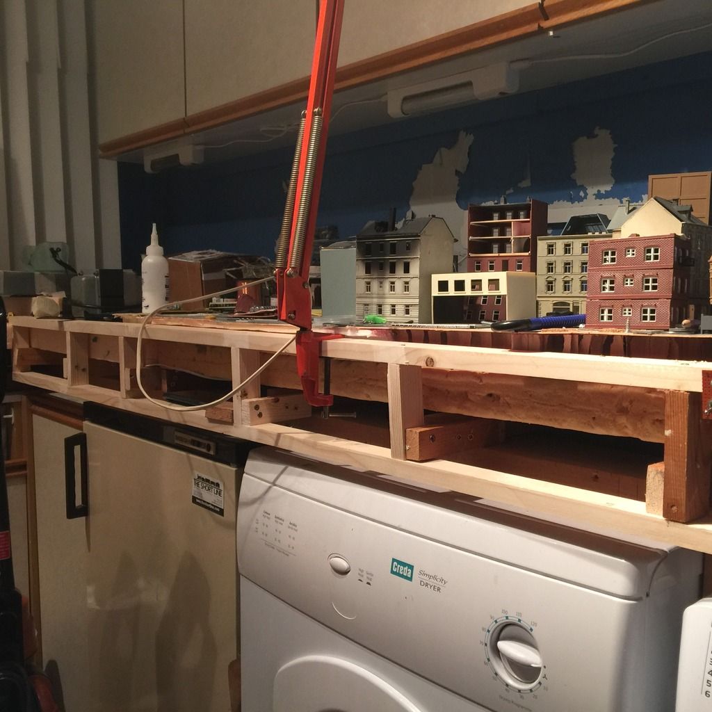
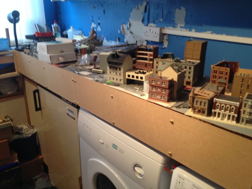
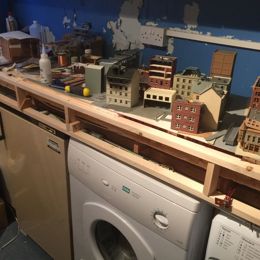
 The City Side of the Layout

This side of the layout has a narrower fascia on account of the washer and dryer height. I will eventually build the city street out to the fascia, giving me about an extra inch of depth, and cut the top edge down in most places to match the road height.


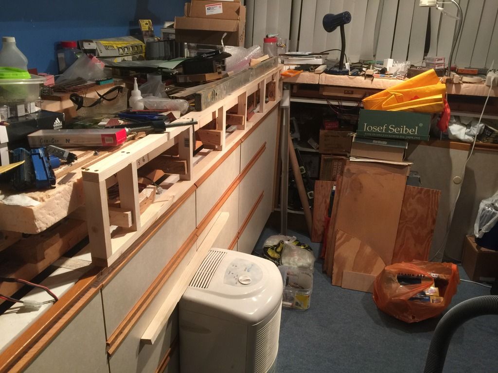
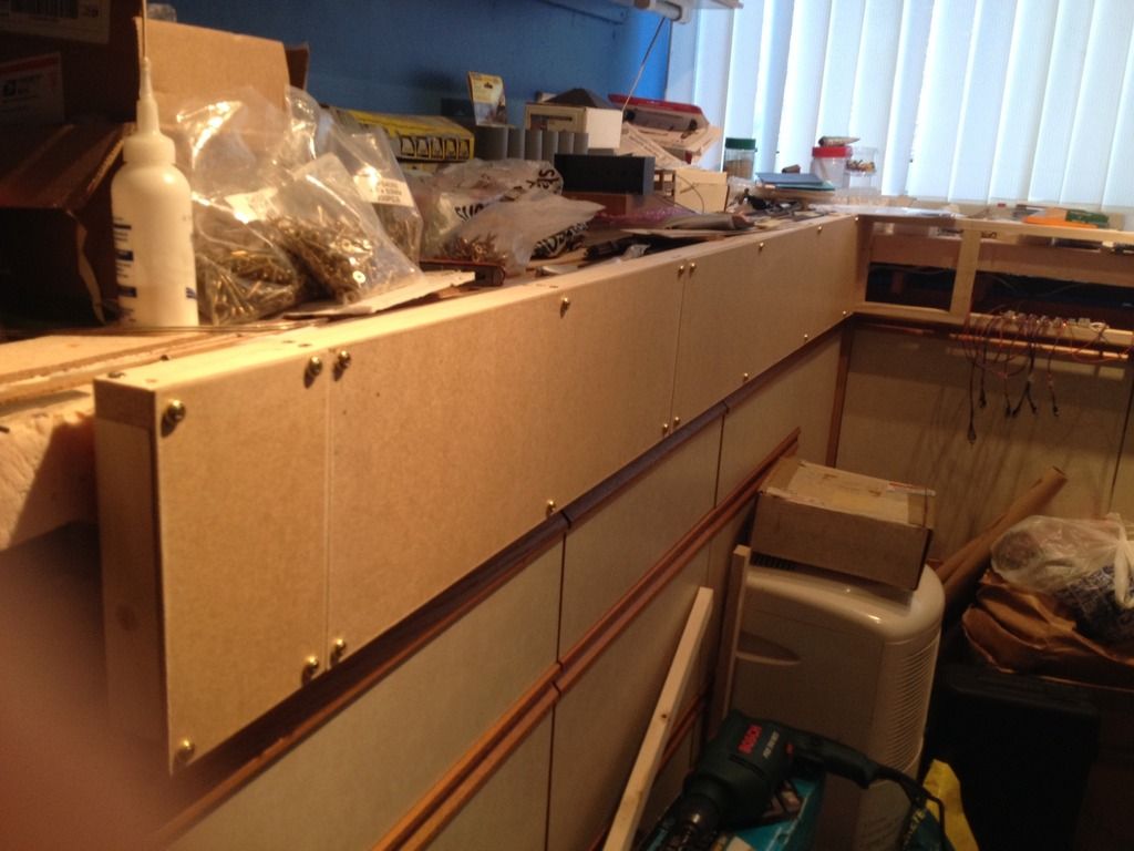
Industrial Park Side of the Layout

The fascia is wider on this and the center section to allow for the increased number of tracks needing to be controlled.


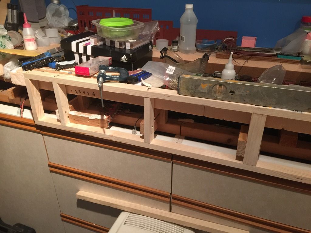
Center Section overall view

The Center section will control the interchange yard and most of the turnouts for the industrial trackage. I have not decided whether to control the interchange yard and industrial tracks from different panels, or to spread the controls across the width of the panel.


From here it's on to the track diagrams, switch installation preparation, painting, and switch wiring.

Wednesday, December 23, 2015

More trackwork - finishing the branch line junction – Part II

Track work:

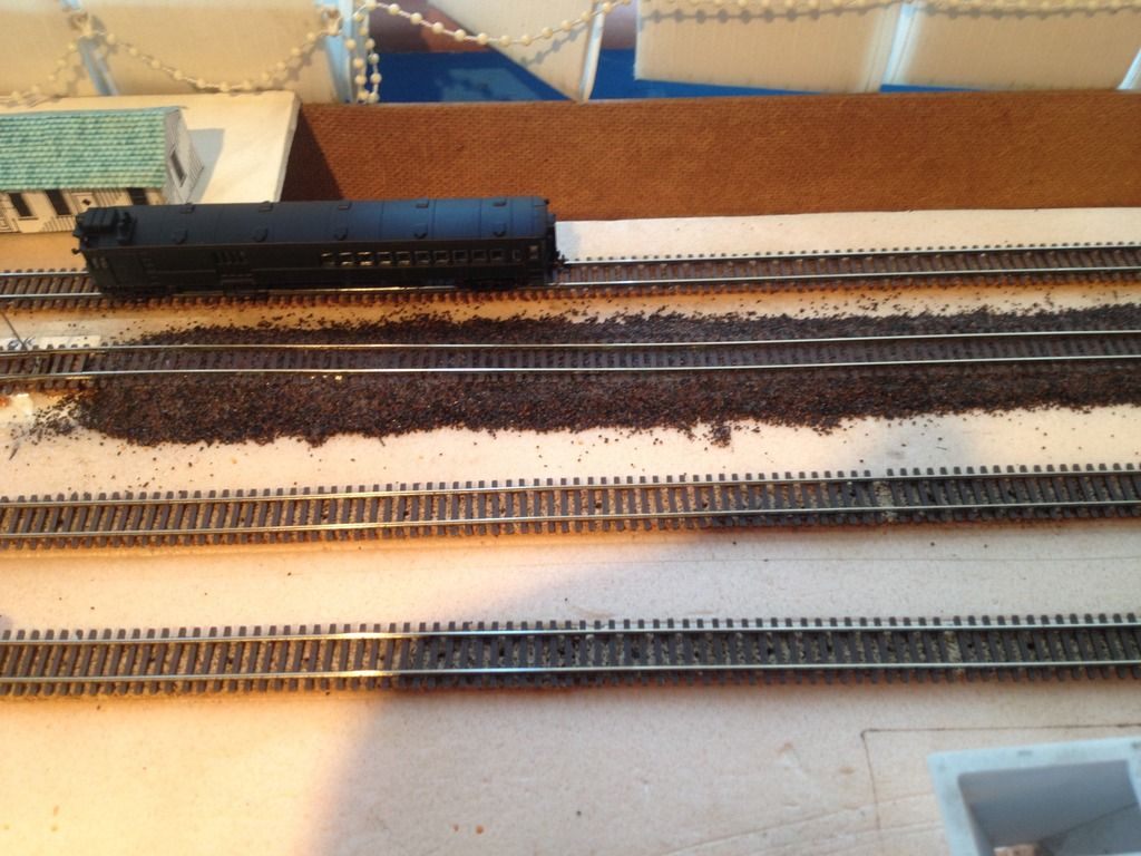
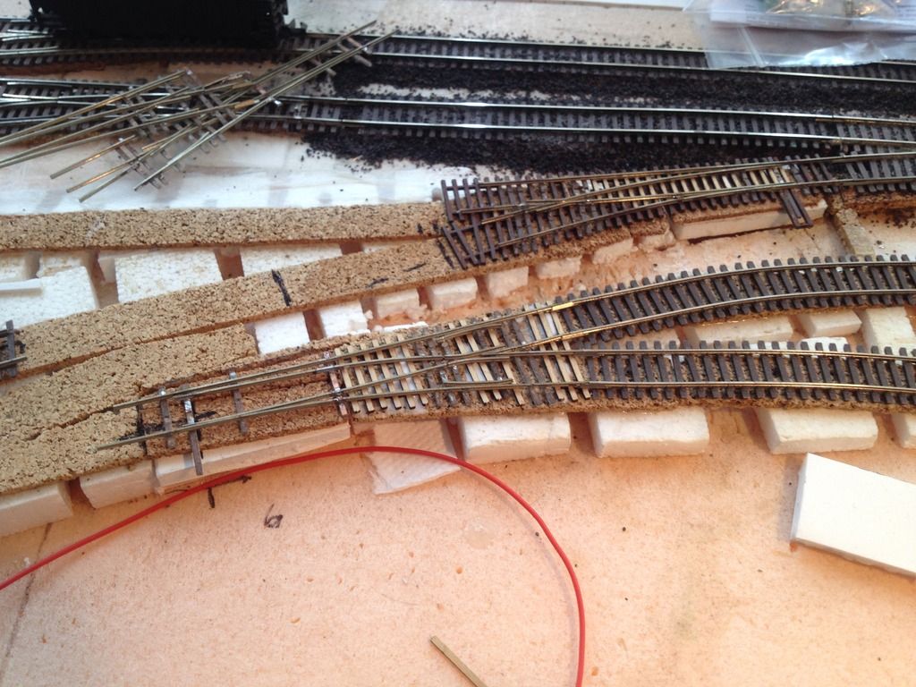
After getting the turnouts fixed in place, the time came to more permanently fix he track. Since this area of the layout is going to portray a weed-grown locale, I thought to deviate from my normal approach of scenery then ballast, effectively killing two birds with one stone by ballasting this track.


The dark ballast was left over from a long time ago, and I have slowly been using it up wherever I want to have a variety, especially since the “normal” color will be light grey. Hopefully I have enough left to finish the branch line terminal and tracks, or I will have to find a replacement.


I also filled under the floating section from the previous post; it went a lot easier than I expected, and can hopefully get everything to a point where I can start the scenic effects, and ballast around the turnouts.

Wiring:


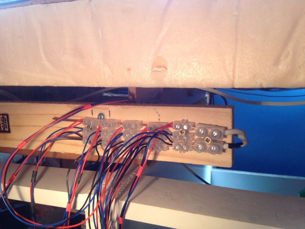
What good are remotely powered turnouts without the means to work them? As I am powering all of them from a separate transformer, I had to run a bus wire around the layout from the outlets to the control switches, which will be mounted on the fascia.
Power Bus Approach:


I came up with the idea of using household mains cable as a power bus to avoid running dozens of jumpers. It definitely made life easier on the loft layout, so I thought I would give it a try where it presented itself.

Planning the code 40 turnout installations

I actually built these years ago, but have delayed installing them due to issues over control. The basic problem was that I could not find a readily available supply of components that did the job in a cost-effective manner, which I was happy with. Having decided that servo motors fit the bill, I can now get on with it.


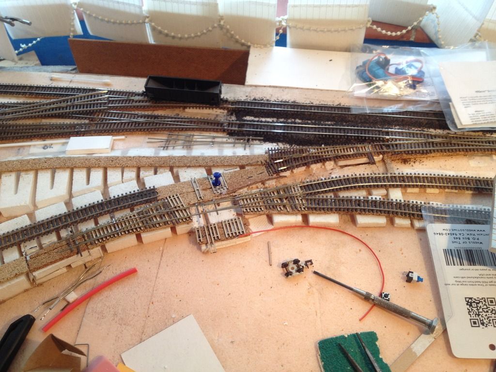
 Having built the first turnout (almost) by the book, I deviated from the following ones, and mounted the wood tie strips directly to the roadbed. This will make the placement easier when it comes time to mount them, as well as simplifying the placement of the servo, as there is no guesswork involved in where the turnout sits in relation to the mounting board.


Here you can get a better look at the placement of the future turnouts from the tie strip placement. I’ve also shown the servo mounting board with tie strip attached.

Change to mounting practice

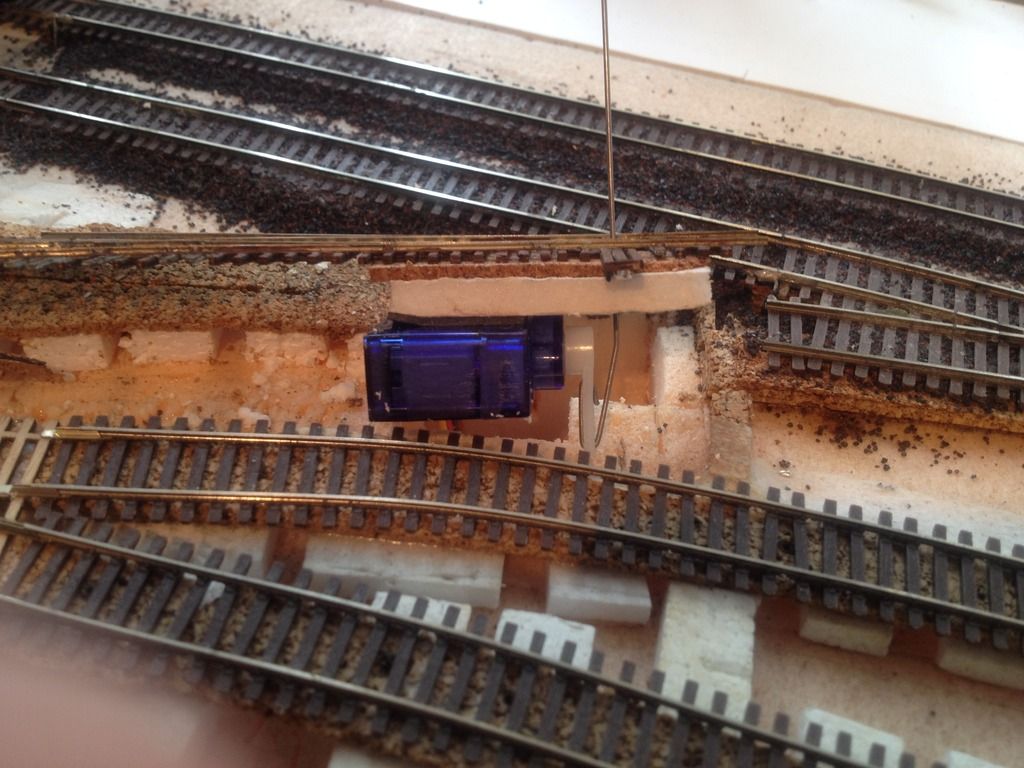
I had been installing the servo on its edge to save space in the footprint, but oddly could not get proper throw in this location using that method. As a possibility I tried turning the servo back on its side, and problem solved. The throw wire is actually thicker than the stock wire provided; I just could not be bothered to change it after I realise it did not solve the problem.


This image shows the revised mounting method.

Tuesday, December 16, 2014

More trackwork - finishing the branch line junction

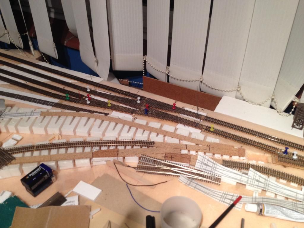
I managed to find some local power transformers that make the servos run really well, so after a bit of experimentation (fun!) with that, I dove back into the finishing up the branch line junction.

I kind of got to this state before Thanksgiving, which took a slight bit of time out of my free-time pool. Getting decorations up for Christmas, etc., well, you know how it is. This was the last "shot" of the work in progress:


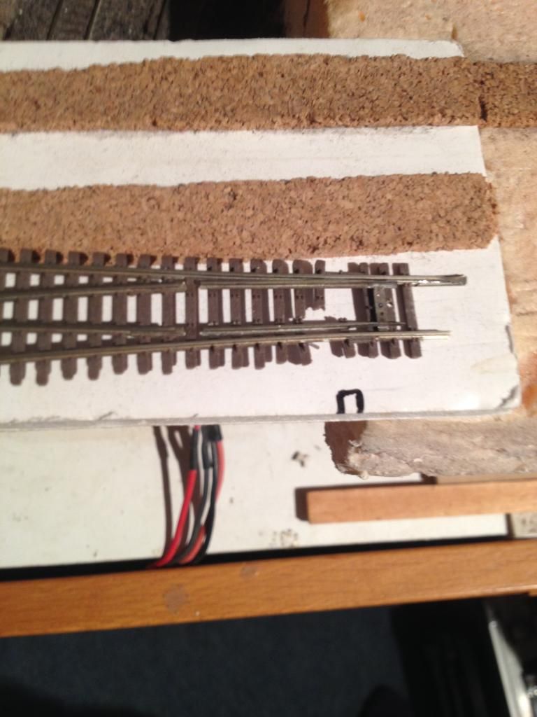
All well and good, right? Not quite. One of the turnouts was not behaving properly. And if it was being a pain now, it could only get worse, right? So I decided to pull it out and attempt to fix it, when this happened:


Well, I can salvage the rail, frog, and guardrails. The project wrapped up in this state, kind of a regression:


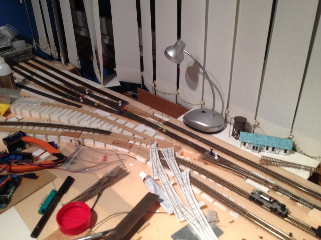
Until today! I got home a bit earlier than usual from work, no major crisis causing me to connect back in from the house, so I decided to get the replacement turnout in place. So I did; back to where I was a few weeks ago!


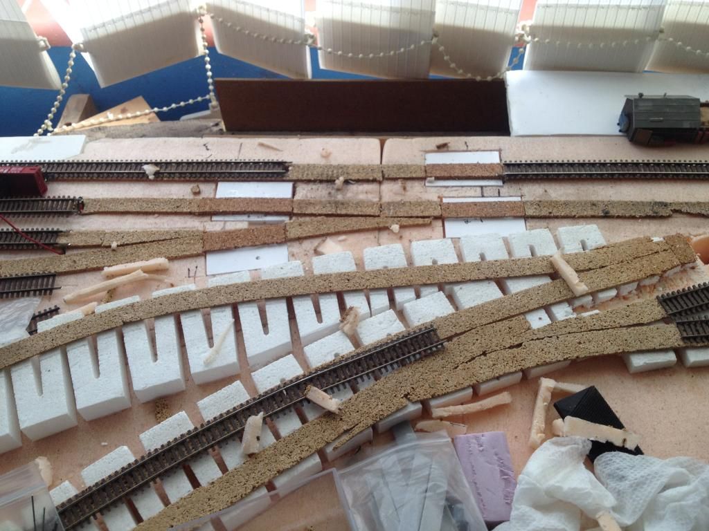
It doesn't feel so much like lost time, since it does seem to work better, so I'll stick to that. I also decided to start on the foam "shaping" that would be needed prior to scenery.

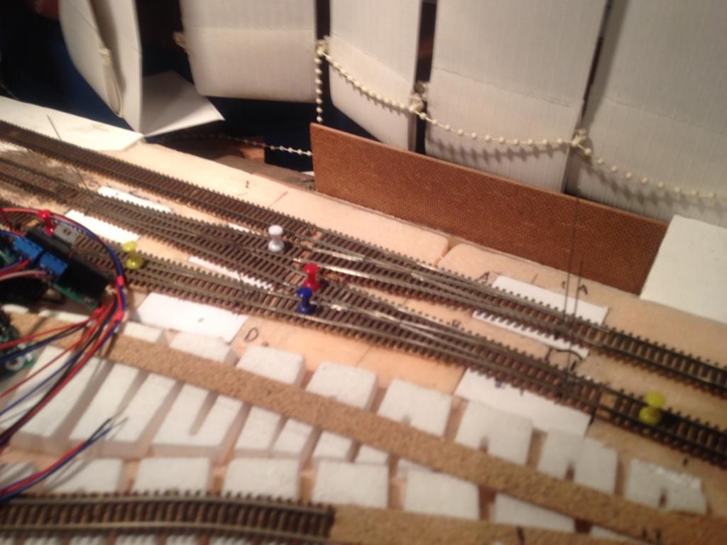
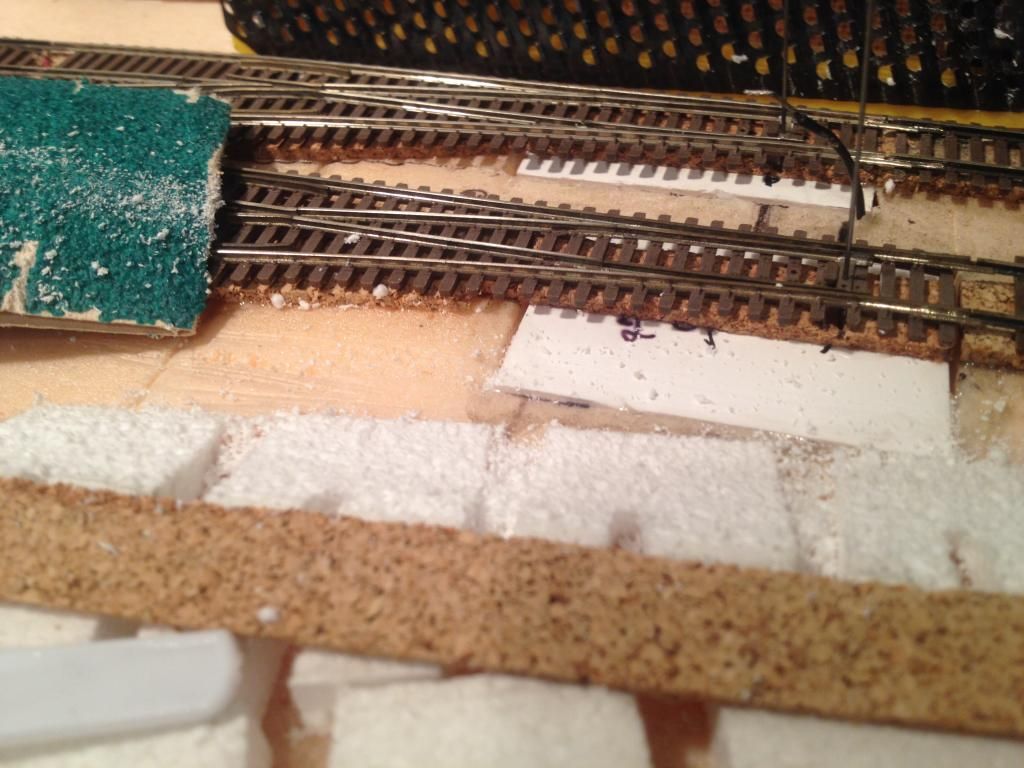
I used the Woodland Scenics risers to elevate some of the track, but it is just too wide for an N scale industrial area, so I sloped the edge of one section down to the base:


The sanding tool was making kind of a mess of the cork as well as the foam, so I only used it to keep a smooth line along the rough shape. I then used the course sandpaper to finish off the shape. Later, once I have hooked up all of the feeder wires and powered up the turnout motors one more time, I cover this with paper, and paint that over with PVA prior to applying the scenery.

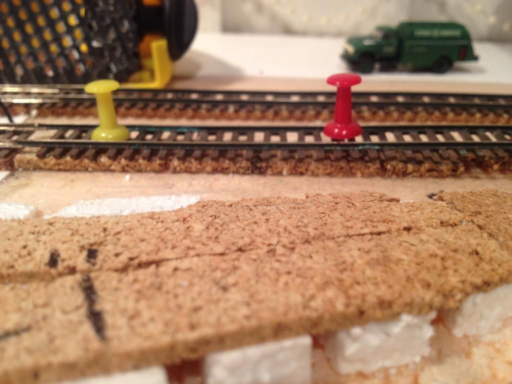
One more challenge to face: the smoothing of one of the "transitions" in height. Gluing the track to the cork left a rather extreme elevation change, so I may resort to using ballast to fill in under this stretch to support it, in a more even grade change:


The track seems to find its own level, so I may trust in its choice on this one occasion, and let it be.


Off to do the wiring, both track and turnout motor SPDT toggles, so won't be much more to show tonight. Hopefully this weekend I'll get trains running on this again,  which has not happened very well in quite a while...

Wednesday, October 29, 2014

On to the Branch Line

It has been a long time (again) since I updated progress. But I have been doing a lot of fun things, though not all train related...

I posted in a few places about experiments with servo motors. So far things are looking pretty good. The Iowa Scaled Engineering products offer different control boards, with two types of relay contacts, to control point & frog polarity, or external contacts. Since I wanted to use the contacts to drive signaling on the main tracks, the MRServo-3 product seems a good match for the mainline and branch line tracks.

So I started installing them:


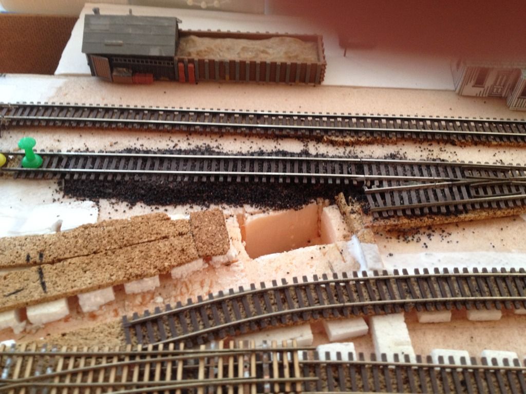
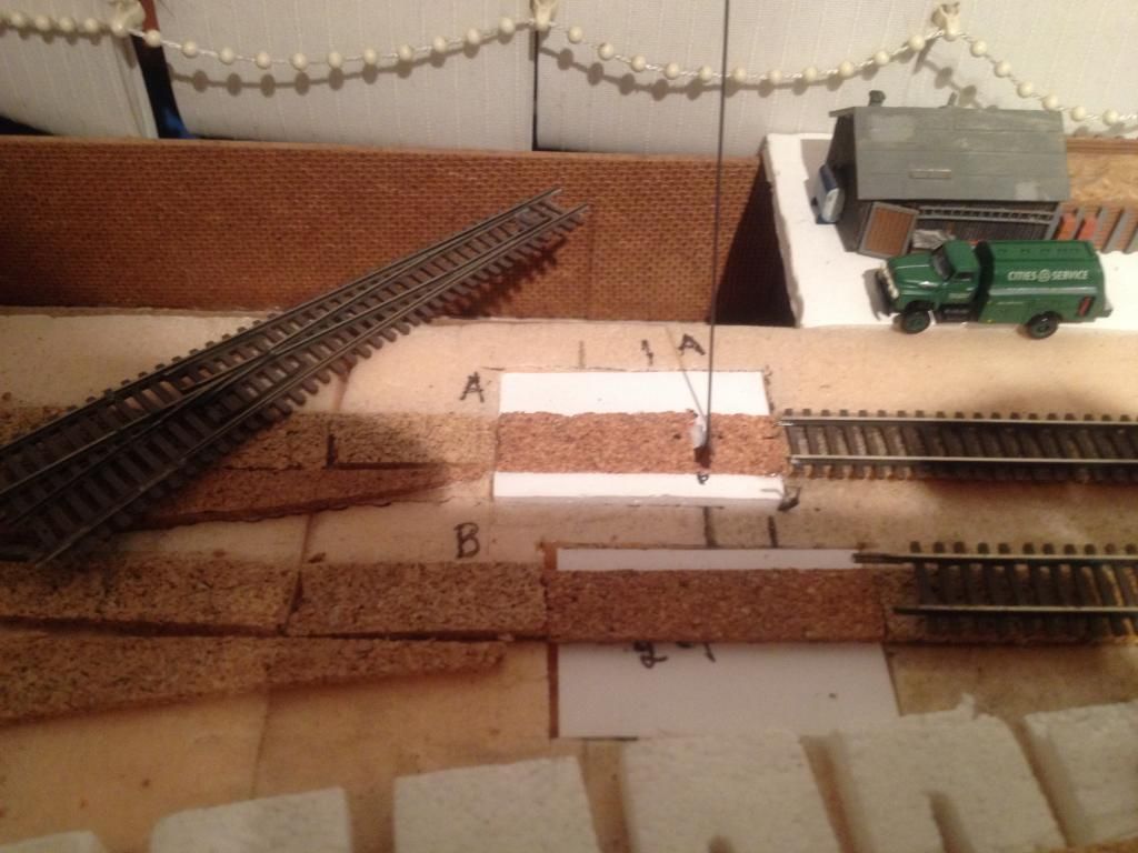
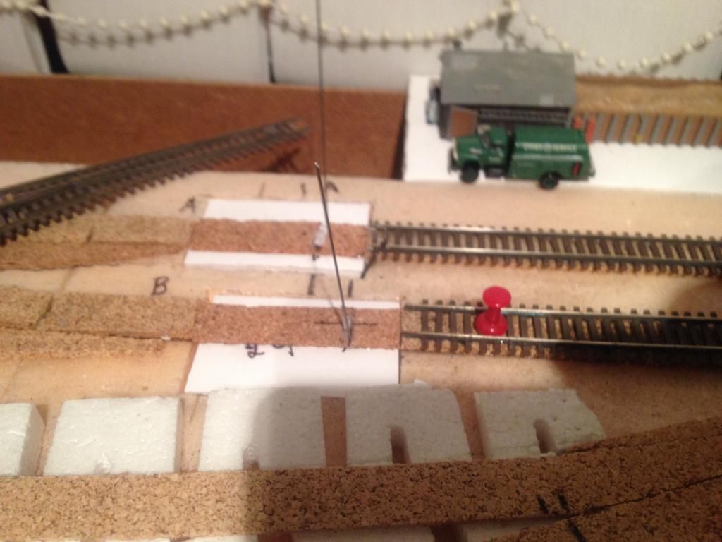
The rectangle of foam core in front of the station mock up will be the first servo install. I will use a different controller board (MRServo-2) on the left-hand installation (where the hole is) with basic power routing and gaps in the rails for the hand laid turnouts.


These four turnouts form crossover and two sidings. One of the mounting holes is in the wrong spot, and has since been moved.


The second installation was much easier than the first, after applying lessons learned.


They are sprouting everywhere! Once I get the other two in, I can look to replace and wire the track back up and test it with some trains. Then one more major challenge to undertake!

Catching up on track work posts...

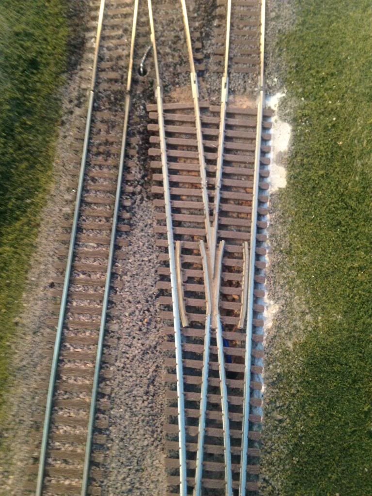
This turnout has been a pain in my neck for some time; some days seems like everything is happy, then on tiger days nothing seems to make a full circuit without hitting dead track.

Turns out my choice of location for a frog power feeder was all wrong (and it was a poor job of soldering!). Just past this connection, between it and the frog, is a manufacturer supplied owner gap. So no power was getting anywhere near the frog. Since I bought the turnouts second hand, I did not gave any documents explaining things.

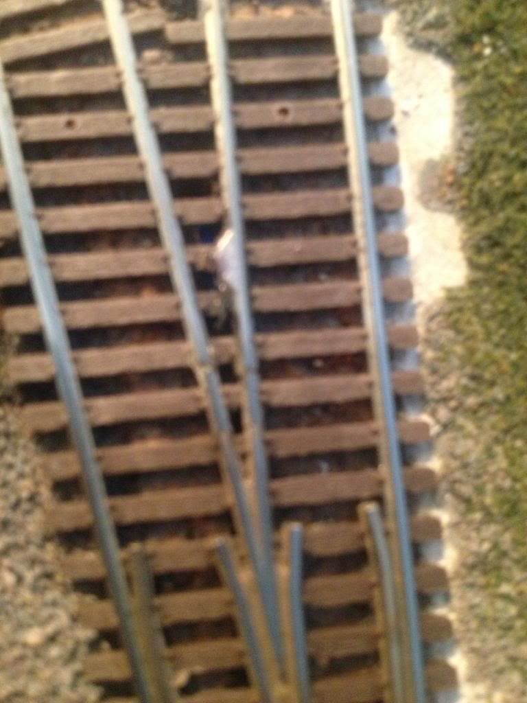
Here's the offending part:


 You can just barely see the gaps about two ties down from the soldered connection

While preparing to replace the turnout after a soldering mishap (to bridge the gaps) I discovered a metal fitting on the bottom, presumably to hold the frog assembly in place. I managed to attach a feeder wire to it, and job done. Solid, working electrical connection completely out of sight!


Armed with new knowledge I proceeded to the next instance of trouble; in this case, bad advice from the Internet, about cutting gaps. As I have learned, the gap is already there, so they, and the insulated rail joiners on the frog rails, are not necessary.

Also, part of the plan is to swap the Cicuitron Tortoise motors for servos, making storage a lot easier as the vertical footprint is significantly reduced.

So I set my sights on replacing this entire crossover:


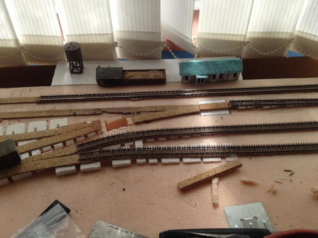
Removing them was the easy part; removing the track and scenery while trying to preserve the scenic features away from the track was a pain.


Getting back to a connected loop:


I replaced all of the removed trackage, and secured it in place with PVA well away from the moving parts. After everything dried I installed three new sets of feeder wires, one at each of the two point ends of the turnouts, and the third on the main rout of the front turnout. There are four blocks on the lift out, but all are connected with other track off the lift out. It's logical, and saves me running extra wiring and the bus for power. Four sets of connections for track power, and one for the turnout motors is complicated enough. Besides, the next big project is motorising the crossing gates...

Where does time go?

I've been spending the time doing more of a chore than enjoyment, i.e. wiring, lately. But while doing so have made some pretty good strides in operational ability on the layout.

One of the thoughts that has floated in my head was converting the layout to run ONLY DCC. This would mean taking advantage of a few newer arrivals in the control front, such as a frog juicer for the power routing in the turnouts, which consequently does not support DC. I could always keep on looking, and trying other new arrivals, but as slow as progress has been, I worry I may never get there...

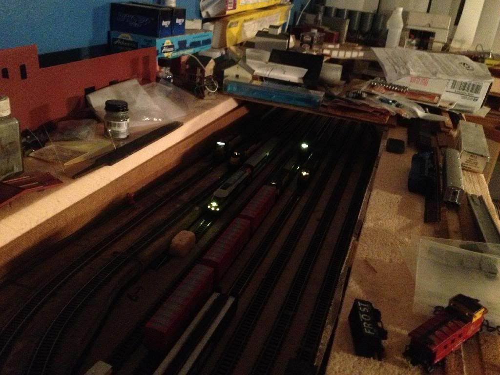
But having fun too; while doing running on just DCC, i managed to get a fairly good line-up of power in the staging yard:


Line up of DCC equipped locomotives; from left to right: Atlas GE Dash 8-40C, Atlas EMD SD50, Kato MPI MP36PH, Atlas EMD MP15, Atlas EMD GP9, and Atlas EMD SD9.I've probably got about twice this number again decoder equipped, so may go the DCC only route on this layout soon, if I can convert a few more GP and SD units easily...

Here is a shot with the flash, so you can what's what:


Tomorrow we may do more running. And a bit more tidying...