Track work:
After getting the turnouts fixed in place, the time came to
more permanently fix he track. Since this area of the layout is going to
portray a weed-grown locale, I thought to deviate from my normal approach of
scenery then ballast, effectively killing two birds with one stone by
ballasting this track.
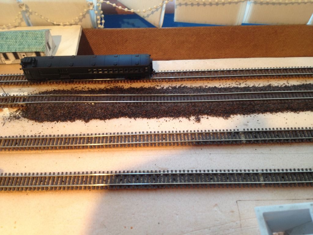
The dark ballast was left over from a long time ago, and I
have slowly been using it up wherever I want to have a variety, especially
since the “normal” color will be light grey. Hopefully I have enough left to
finish the branch line terminal and tracks, or I will have to find a
replacement.
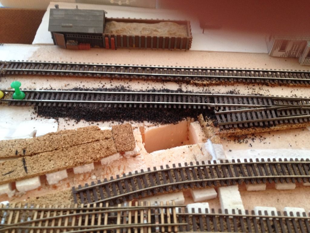
I also filled under the floating section from the previous
post; it went a lot easier than I expected, and can hopefully get everything to
a point where I can start the scenic effects, and ballast around the turnouts.
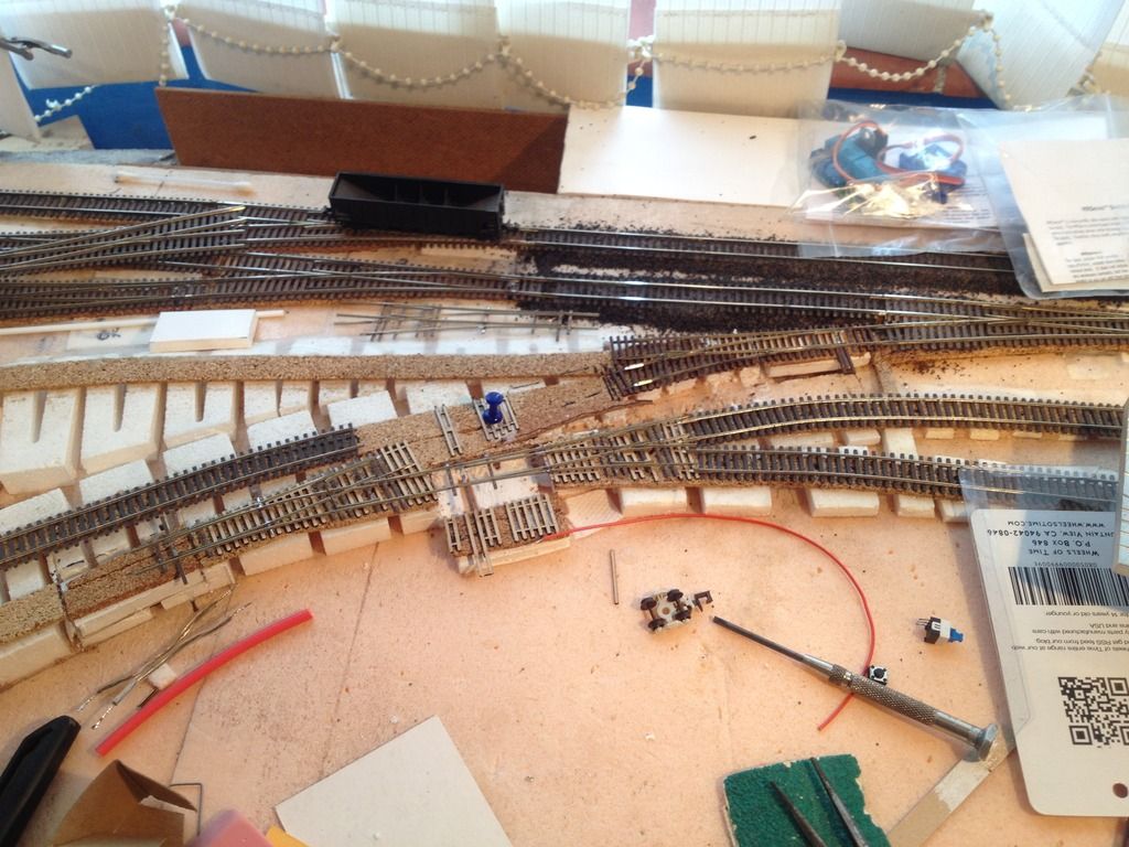
Wiring:
What good are remotely powered turnouts without the means to
work them? As I am powering all of them from a separate transformer, I had to
run a bus wire around the layout from the outlets to the control switches,
which will be mounted on the fascia.
Power Bus Approach:
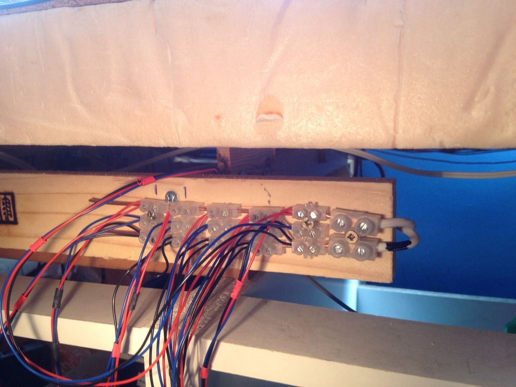
I came up with the idea of using household mains cable as a
power bus to avoid running dozens of jumpers. It definitely made life easier on
the loft layout, so I thought I would give it a try where it presented itself.
Planning the code 40 turnout installations
I actually built these years ago, but have delayed
installing them due to issues over control. The basic problem was that I could
not find a readily available supply of components that did the job in a
cost-effective manner, which I was happy with. Having decided that servo motors
fit the bill, I can now get on with it.
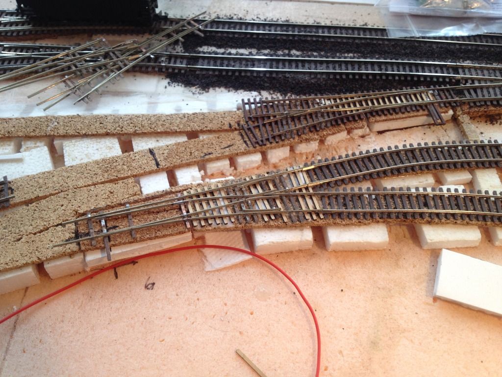
Here you can get a better look at the placement of the
future turnouts from the tie strip placement. I’ve also shown the servo
mounting board with tie strip attached.
Change to mounting practice
I had been installing the servo on its edge to save space in
the footprint, but oddly could not get proper throw in this location using that
method. As a possibility I tried turning the servo back on its side, and
problem solved. The throw wire is actually thicker than the stock wire
provided; I just could not be bothered to change it after I realise it did not
solve the problem.
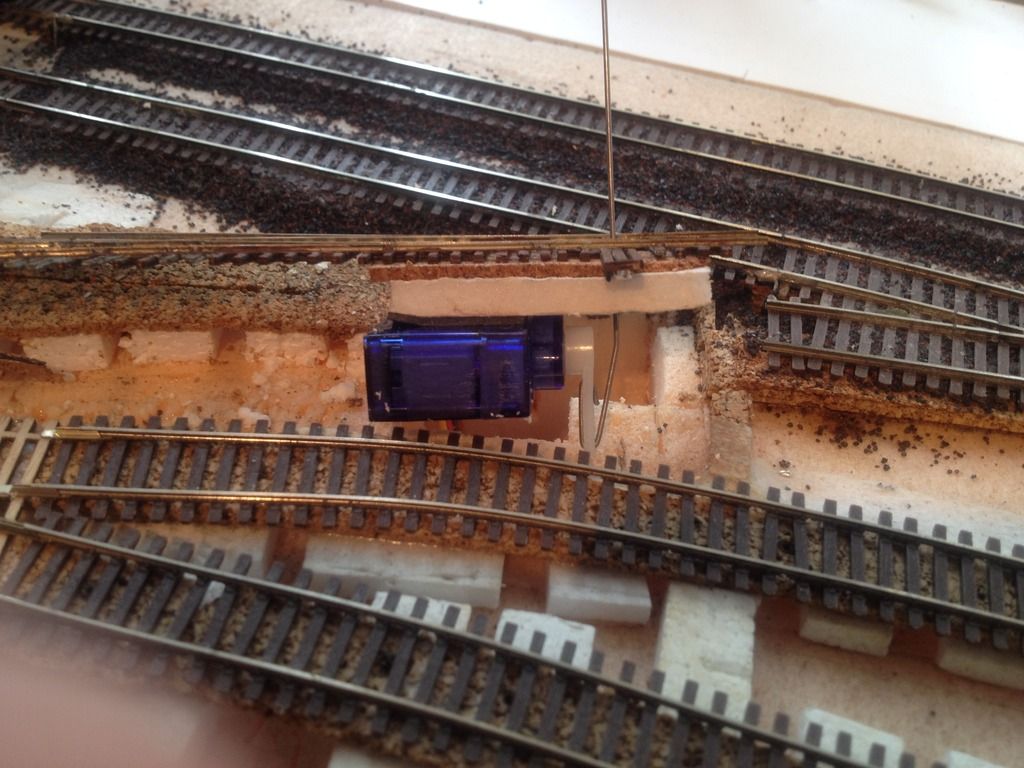
This image shows the revised mounting method.