Introduction:
For most of the early years N-Scale structures were dominated by European imports that looked, well, European. While many areas of the United States and Canada have strong European backgrounds, some of the building features and materials portrayed look out of character on a North American layout.
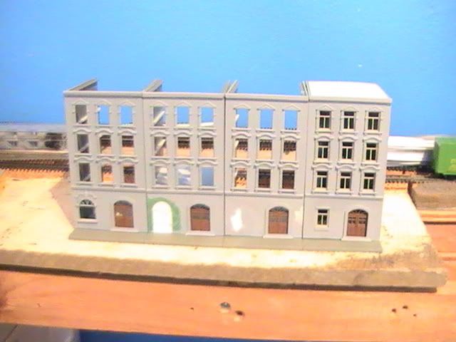
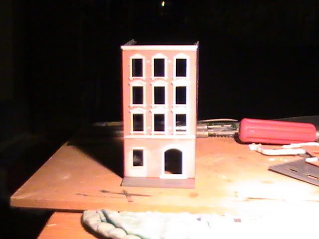
Some simple modification (i.e. kitbashing) can make dramatic improvements in the appearance of a very European looking structure:
Into something less out of place on a North American layout:
I’ll go through the step-by-step process I followed to make these changes.
Inspiration:
Some of the inspiration for the project:
My biggest concern WAS the round-topped (arched) entry door, but these even had arched windows! I might cut the vertical muntin to make two panes instead of three, but I'll keep looking for more examples like the kit windows first.
My original inspiration pic seems to have gone AWOL; so here are a few that give plausability to the project:

http://sjconnor.files.wordpress.com/2007/09/chinatown-balcony-wp.jpg - a building apparently in Chinatown, Vancouver
Notice the the three pane windows, with a vertical muntin separating the lower section, with approximately the same proportions as the kit windows. So not completely alien...

http://shoutyoungstown.blogspot.com/2011/07/federal-building-is-fully-rented-before.html
A much cleaner looking structure, and granted, no fancy trim, but the arch-topped windows at the top floor. I may have to try this one some day...
Preparation:
I added some of the "out of the box" details that would use on the finished structure, both for ease of working and to add strength to the finished product.
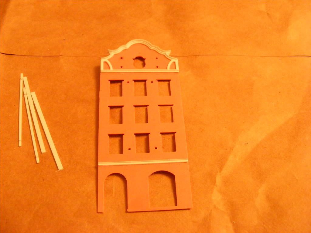
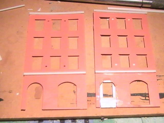
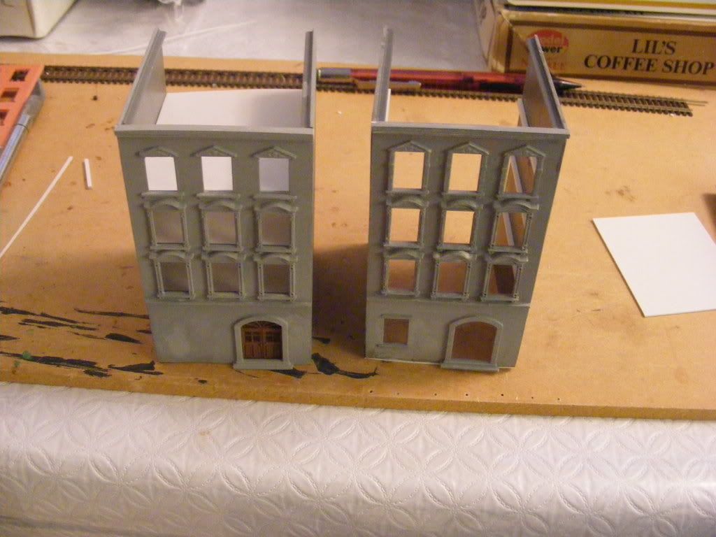
The first pic below shows the starting condition of the parts to be modified:
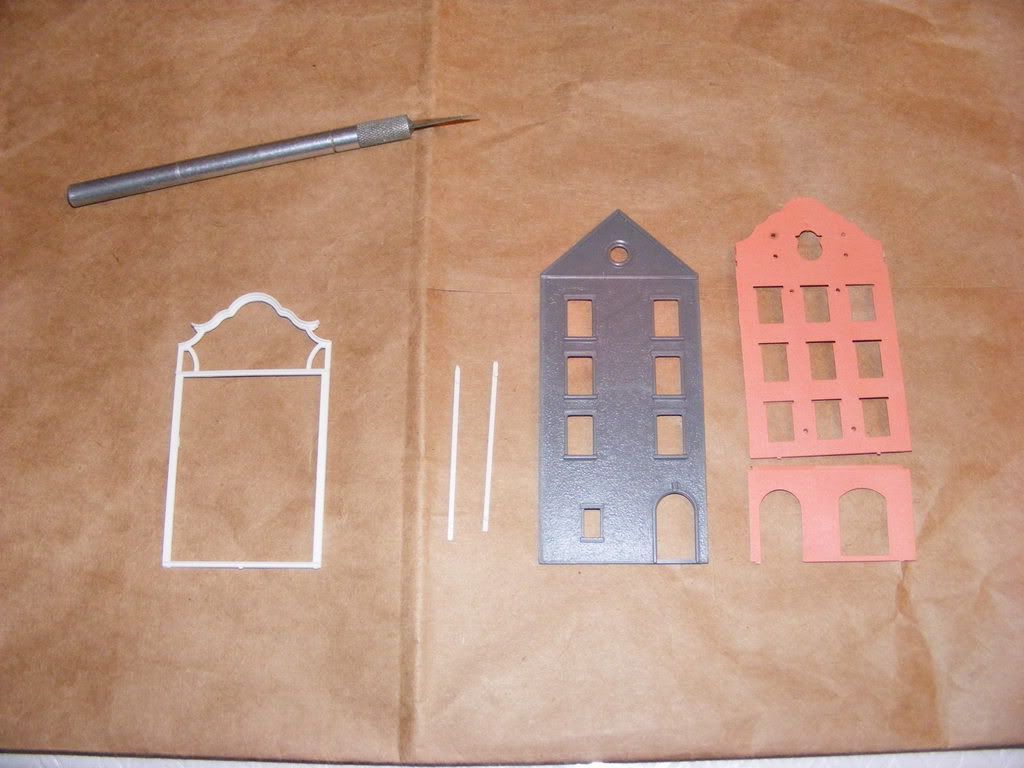
For reference, the right-hand opening on the front (pink) wall will become the doorway. The other larger opening will be partially filled in and a window (like those in the upper floors, but without the 'detail' surround) will be added. Both front and back walls will need trimming to remove the peaked roof, which by itself is both the biggest change and the feature that made the structure 'passably' American.
I also trimmed the front 'trim' section to retain the cornices but remove the vertical trim bars. The top curved molding was left to give me something to hold on to, but will eventually be trimmed off when the wall is de-capped. Below is the image of the cuts made to separate the cornices from the one-piece molding:
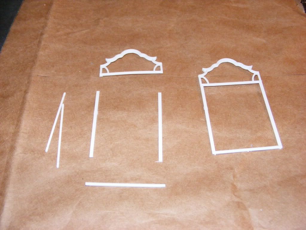
I then joined the lower and upper front walls, and used the edge of the joint as a guide to position the lower cornice. This is glued to the surface of the front wall. I removed the vertical bars as I thought the glue would seep under the edges and mar the surface, and I wanted to retain the molded stucco effect.
I also cut down the separate vertical trim bars and cemented the mounting lugs into the holes on the wall surface. I trimmed these as small as possible to minimize the marring of the surface, but still left enough to handle the piece.
Unfortunately my progress was limited by the availability of cement; I was at my son’s house and packed up everything I needed, but the bottle of plastic cement tipped over in the bag on the way here and evaporated, leaving me with the alternative of nasty, thick, filler based cement. Yuck! That is the stuff that leaves strings and a blob of itself behind if you are not careful, so I carefully used that and did the bits you see here, and will carry on with construction when the new cement and filler (found a source for squadron green and white over here: woo hoo!). Hopefully the next
installment will be within the week...
Cutting the walls to the new shape:
Right, time for some progress. And regression.
I had a fairly productive evening on two of the kits, and have almost a shell completed.
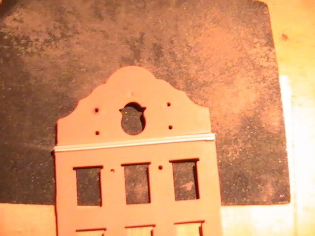
I have trimmed the white 'details' off the top section of the front wall in preparation for topping it. The peak is going to go, and a piece of strip styrene will build up the front.
The rear wall was also peaked, so it had to get cropped as well. Thankfully the trim makes a nice guide for the razor saw, but be sure to not cut into the trim itself, as it will be visible if the roof is visible...
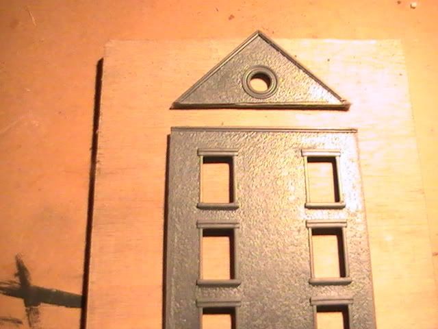
The regression: I never really like the arched, euro-style back door, and the kit contained extra castings for doors and windows, one of which (IMHO) was much more plausible. But it meant filling the hole. And shaving off the raised trim. I used a flat 'chisel' blade to carefully shave the raised detail off around the door frame.
Since the kit wall is approximately .040" thick I used a similar size of styrene strip; you could use the plastic cut off the roof peak, but that seemed a bit more complicated than trimming strip stock to match a rounded whole. After the glue dried I filled it with Squadron white putty (I love this stuff!). Once the was dry (within a couple of hours) I sanded the surface smooth with very fine sandpaper from Testors.
This also shows the future door. I am considering retro-fitting the same door to the other structures almost completed...
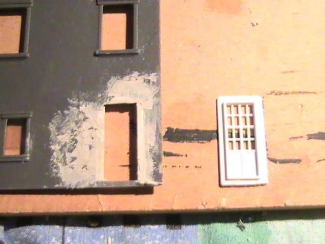
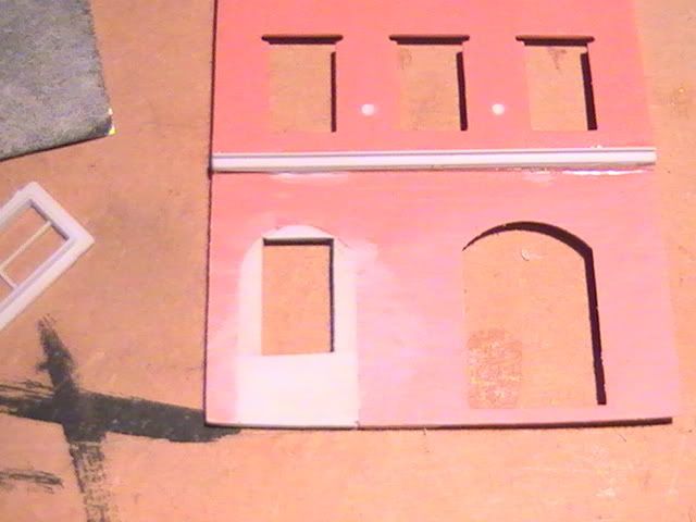
The front of the structure has two arched doorways, and I replaced one with a standard window from the extras supplied with the kit. This meant filling and smoothing, but thankfully not the trimming as the raised detail is a separate piece. You can see the two in comparison:
I made windows opening the same height as an adjacent structure, which worked out to about .040" below the existing window frame. This 'size' is becoming part of my n-scale life in a big way, especially considering it is also the height of code 40 rail! But that's another story...
Once the cement was dry I filled the gaps with more white putty, and smoothed it after drying.
I also discovered it is MUCH easier to cut the hole to a rectangular shape instead of trimming the plastic strips to fit the arched hole. Go figure! I also used the strip from the sides of the front detail (cut off earlier) to fill in the sides, and they were exactly the right size. And besides, recycling is better, right?
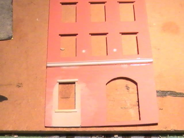
After I was satisfied with the finish of the surface I used ACC to attach to small strip to the top and bottom of the window opening to match other structures. It made a huge difference in making the window look 'finished'.
Attaching the rest of the front detail was as the kit instructions intended. The windows details have small pins to hold them in place which makes the job a LOT easier...
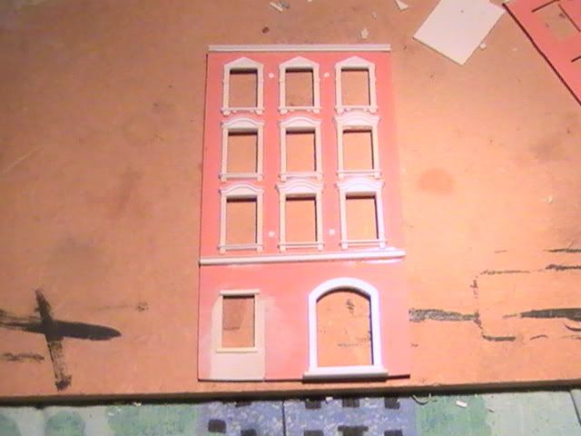
Likewise, attaching the sides is straightforward. I did discover that I had sanded too much off the bottom of the front wall under the new window, and will have to be more careful on subsequent kits and fill this in. I also added a strip of HO scale 6x8 on its side to build up the top of the front detail.
In the next instalment I'll add interior floors and walls to break up the open-ness of the structure's interior, and hopefully discuss lighting...
Floors:
I have spent considerably more time doing other than Model Railroad stuff this week, so I did not get a chance to even think about lighting. But what I DID do was cut the floors for the existing structures, and add the floor bracing for the two still "in progress", in order to document the progress.
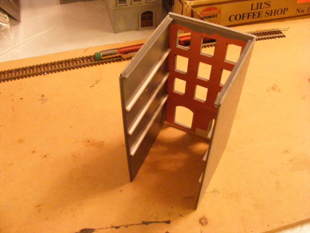
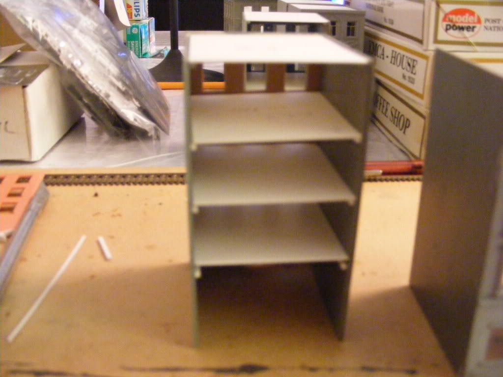
I used strips of .060" plastic square stock to position the interior floors at approximately the right height, about balanced between the rows of windows. You can see this below:
This is much easier to do while the side walls are lying flat, instead of adding it later, when the building is assembled. This way you can easily use a square to enure the floor will be roughly level, or at least perpendicular to the wall. You can see the bracing in a standing structure:
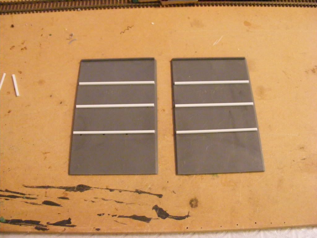
I then cut .020" styrene sheet for the floors. Once you have one cut you can use it as a guide for the size of the others. I did not glue them in yet; they only sit loosely on the bracing at present.
You will also need a new roof, as this WAS the whole reason for doing this, right? DO NOT use the floor as a guide for the roof, as this needs to be a touch wider than the floors. It sits partly on top of the side walls...
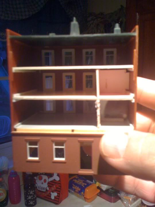
A view of the floors:
Why do the interior floors?
It is not necessary, but DOES make a considerable visual impact on the finished structure; as shown here:
Looking 'through' the structure you will not be able to see the 'downstairs' windows, only those on the same floor. I will be adding interior walls as well, in order to break up the interior and add more detail, but you should AT LEAST consider adding floors and painting them if you go no further on the inside detailing.
An Alternative method:
I was experimenting with some heavy card the wife’s employer uses for advertising, and decided that in addition to a wonderful sub-base for the structure ‘blocks’ and sidewalks, it is an excellent material for interior walls! So I added floors and some divider walls using this same card. It will block the light better than plastic would, and is just as easy to use as plastic. From the outside you cannot tell the difference.
Card:
Plastic:
About the only difference is the thickness of the material, which allows the better light control. It is also a bit easier to work with, using PVA or Elmer's glue as opposed to plastic cement. Adding vertical walls was also a simpler process, as it involves a bit of trimming and fitting, and went together with a little less hassle than the plastic walls.
Next: Stairs and interior walls...
No comments:
Post a Comment